Student Engineer
Design Portfolio
Praxis I, CIV102 & Praxis II — Engineering ScienceNavigation Guide
This portfolio is organized as an engineering handbook detailing the concepts, tools, models, and frameworks I used so far in three engineering projects across three courses. Use the navigation bar below to jump between sections. Each CTMF is examined using a What / So What / Relation to Position structure, with an At a Glance summary at the end.§ 1 — Position in Context
The Empathetic Optimizer
Introductory Vlog
Figure 1. Beginning-of-semester vlog — documenting my initial position before Praxis I, CIV102, and Praxis II reshaped my engineering identity.
At the beginning of the semester, I recorded a vlog to document my position on engineering design. I stated: "I see engineering design as an interpretive process — understanding a problem, noticing small details, and using my knowledge and skills to decide how a solution or improvement can be designed."This initial position was highly analytical, deeply iterative, and strongly rooted in my lived experiences. As a Varsity Blues tennis player, I learned Perry's concept of Relativism firsthand; I realized early on that there is rarely a single "correct" duality to winning a point, but rather a constant weighing of trade-offs based on evidence and experience. Similarly, my background in rock climbing taught me that meaningful improvement rarely comes from massive overhauls, but from tiny, precise iterations — like shifting my hips slightly into the wall to send a route. To me, engineering was like a proof-based calculus class or a climbing route: a rigorous, iterative optimization of details to find the best possible path.This "Optimizer" mindset gave me a fantastic work ethic and a sharp eye for mechanical efficiency. However, at the end of that same vlog, I noted a critical self-awareness: "I feel my current approach makes it difficult to scope outside of my personal experience."Because my problem-solving approach was so heavily tied to my independent athletic and academic routines, I was accustomed to acting as both the designer and the sole user. My paradigm completely expanded during Praxis II while developing the "Fluffy Box" — a device designed to clean climbing holds at Basecamp. Because I am a climber, my instinct was to rely entirely on my own n=1 experience to optimize a solution. But to truly solve the problem of airborne chalk plumes for the wider community, I had to deliberately step outside of my own head.I developed an Empathetic approach to design by treating my stakeholders not as subjects to be observed, but as active partners. When we brought our prototypes to Basecamp, their feedback directly drove our iterations. When climbers expressed that our initial motor was too loud, or that our camera-mount joint was too rigid for the angled Moonboard, I didn't rely on my own assumptions; I listened, swapping for a quieter motor and a fluid ball joint. Furthermore, to break out of my personal mechanical biases, I developed an appreciation for the artistic side of engineering through Biomimicry. Looking at how fine structures in nature trap particles led us to the microfiber "fluff" concept — generating vastly more creative ideas than my rigid logic ever could have alone.
Today, my engineering identity is the synthesis of this journey: The Empathetic Optimizer. I have not abandoned my meticulous, iterative, trade-off-weighing roots from tennis and climbing; rather, I have expanded them. I believe that engineering design must be executed with rigorous, iterative mechanical efficiency, but it must be anchored by a deep, collaborative empathy that scopes far beyond my own personal experience. This portfolio explores how my design experiences across Praxis I, CIV102, and Praxis II challenged my biases, and how I now deliberately select Concepts, Tools, Models, and Frameworks (CTMFs) to act as guardrails — ensuring my pursuit of optimization always serves the human element.My BiasI have a historical tendency to let my drive for "Optimization" override my "Empathy." Once I see a mechanical path to efficiency, I often rush to converge, ignoring user comfort, aesthetics, or the quieter voices on my design team.
§ 2 — Praxis I Design ExperienceUniversity students who consume multiple daily nutritional supplements (pills and powders) experience a cluttered, time-consuming morning routine. This friction leads to a high rate of task abandonment.The design needed to minimize user steps and dispense a highly variable dosage (5g–30g of powder, 1–6 pills) in under 40 seconds, while taking up less than 0.02 m³ of dorm shelf space.We mapped the user experience, breaking down the morning routine into timed steps. To diverge from standard shaker bottles, we utilized structured 6-3-5 Brainwriting. We then evaluated concepts including a Disk system, a Pez-style dispenser, and a Slider with Slit. After a critical proxy-test of the Pez machine and rigorous convergence using a Pugh Chart, we selected our final design.A 2-in-1 Rotating Cylinder Dispenser. It features a nested 24-compartment dial system. The user rotates the dial to a marked day, aligning an internal cutout to drop both pills and a customized powder dose simultaneously into a cup.A compact, single-piece unit that reduced the morning dispensing routine from an average of 206 seconds down to 3.06 seconds.
The Rotating Cylinder Supplement Dispenser
One-Page Project Summary
Opportunity
Frame
Process
Product
Result
Product Images
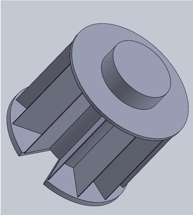
Figure 2. CAD render — angled view showing the internal compartment structure and top dial.1 / 3
CTMFs from Praxis I
1
6-3-5 BrainwritingCTMF 1
What: The Observation
6-3-5 Brainwriting is a structured, silent divergence technique designed to maximize idea generation while preventing uneven group dynamics. In our team of 6, each member sketched 3 ideas, and we silently passed the sheets 5 times, building upon the previous person's concepts. My evidence is the 6-3-5 instruction and scoping document used to guide our session.Evidence of Use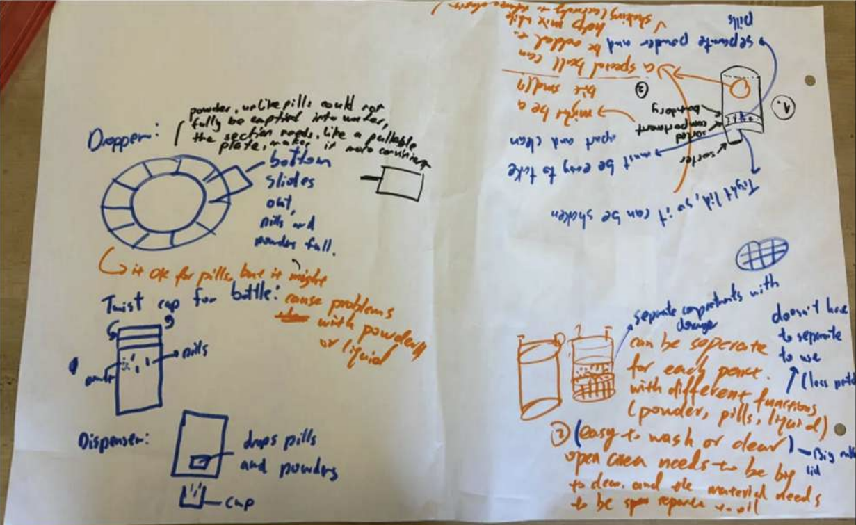 Figure 5. 6-3-5 Brainwriting session with two other teammates from last semester.
So What: Analysis
Early in our process, our team was paralyzed by Anchoring Bias. Because our initial discussions started by evaluating existing products, all of our early verbal ideas were merely slight, uninspired adaptations of standard reference designs (like segmented shaker cups and basic pill organizers). 6-3-5 Brainwriting deliberately broke this anchor. Because it enforces strict silence and rapid, forced iteration, it physically prevented us from lingering on or verbally defending those initial, safe reference designs. It forced us to abstract and combine discrete functions, ultimately allowing genuinely novel ideas — like the genesis of our rotating cylinder — to emerge organically on the page.Relation to Position
This tool profoundly shifted my approach to teamwork. My historical "Optimizer" bias is to verbally solve problems out loud immediately, which inadvertently anchors the team to my first confidently stated idea. 6-3-5 Brainwriting forced the "Empathetic" side of my identity into my team practice. It gave the ideas of my less-vocal teammates equal weight and physical space to develop, proving to me that structured silence often yields vastly superior engineering divergence than vocal debate.At a Glance
Strength
Eliminates Anchoring Bias and vocal dominance by enforcing silent, parallel ideation across all team members simultaneously.Weakness
The rigid structure can feel artificially constrained during early conceptual phases when open dialogue would naturally surface important framing questions.Takeaway
Structured silence is a more powerful divergence tool than open debate, especially when one team member is a confident, fast-thinking optimizer.2
The Pugh ChartCTMF 2
What: The Observation
The Pugh Chart is a rigorous convergence matrix used to evaluate divergent concepts against a baseline design (the datum) across weighted criteria. My evidence is a digitized Pugh Chart from our final report, which uses the Rotating Cylinder as our datum (baseline 0) to evaluate the Disk, Pez Machine, and Slider with Slit.Evidence of Use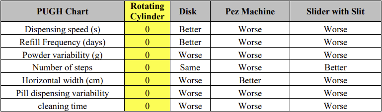 Figure 6. Praxis I final report — Pugh Chart with the Rotating Cylinder as datum. The Disk's negligible advantages and severe dorm-room dealbreakers became visible only through the discussion the matrix forced.
So What: Analysis
The Pugh chart was instrumental in helping us systematically converge, but it taught me a crucial lesson about data interpretation: different charts and views reveal different realities. Looking strictly at the matrix, the "Disk" design actually scored "Better" than the Rotating Cylinder in our top two criteria: Dispensing Speed and Refill Frequency. A purely automated reading of the chart would have selected the Disk. However, the matrix forced a deeper, targeted discussion. Upon closer review of our raw reference values, we realized the numerical margins by which the Disk was "better" in those top two categories were negligible. Conversely, the Disk's "Worse" ratings in Horizontal Width and Powder Variability were severe dealbreakers for a dorm room setting.Relation to Position
The Pugh Chart refined my "Optimizer" mindset. It demonstrated that an engineer cannot just count up the highest number of "Betters" on a spreadsheet and blindly declare a winner. True convergence requires using the matrix to highlight discrepancies, and then applying qualitative, empathetic engineering judgment to weigh those trade-offs. I now use Pugh charts to guide deliberate discussion, rather than to dictate a final answer.At a Glance
Strength
Forces systematic, criterion-by-criterion comparison of all designs, making implicit trade-offs explicit and visible to the entire team.Weakness
The datum choice and criteria weighting can be unconsciously manipulated to favour a preferred design, making the tool vulnerable to confirmation bias.Takeaway
A Pugh Chart is a discussion tool, not a decision machine — the most important output is the conversation it forces, not the final numeric score.3
Low-Fidelity Proxy TestingCTMF 3
What: The Observation
Low-Fidelity Proxy Testing involves rapidly building vastly simplified physical models using cheap materials to test specific functional assumptions before committing to high-fidelity prototyping. Proxy tests are necessary to get a relative idea of how certain concepts perform compared to other concepts. My evidence is our experience building a crude physical proxy of the Pez-style machine to test its sliding mechanism with actual whey protein powder.Evidence of Use
Figure 7. Proxy test video of dispensing speed of four design concepts.
So What: Analysis
This test showed that perceived efficiency doesn't always translate to real performance. While the PEZ dispenser seemed ideal, reliability and adaptability are just as important as speed. Although these were low-fidelity proxy tests and not fully accurate representations of final performance, they are still valuable for comparing ideas and identifying feasibility early on. The results helped us recognize key design priorities—balancing speed with consistency and robustness—and reduced uncertainty by challenging initial assumptions through physical testing.Relation to Position
This proxy test reinforced my value of being highly detail-oriented in engineering design. It showed me that small, overlooked factors—like friction, pill shape variability, or material behavior—can significantly impact performance, and these details are often invisible in CAD models or simulations. I realized I cannot fully optimize a solution behind a screen alone; real-world complexity requires physical interaction to uncover hidden issues.At a Glance
Strength
Simple to test and useful when it is hard to find relevent data through secondary research.Weakness
Results are highly sensitive to the fidelity of the prototype.Takeaway
Although proxy tests might not provide accurate values since the prototypes are low fidelity, remember that they are useful for comparing between concepts.§ 3 — CIV102 Design ExperienceNovember 2025 | Teammates: Brandon Chow, Lucas CuiDesign and construct a bridge spanning 1200mm that can support a 400N train using strictly limited materials: one 1022mm sheet of 1mm thick matboard and one vial of contact cement.The design needed to maximize the failure load across 8 specific failure modes (e.g., tension, shear buckling) while maintaining a strict material usage limit (<100% of the provided matboard sheet) and accounting for the necessity of a splice connection due to material length limits.We used a baseline "Design 0" and developed a MATLAB script to rapidly iterate and calculate Factors of Safety (FOS). Over 8 iterations, we adjusted web height, flange thickness, and diaphragm spacing, balancing structural integrity against material constraints.A 1252mm pi-shaped cross-section bridge featuring a triple-layered top flange, 120mm web height, 75mm gap between webs, and precisely spaced diaphragms (170mm).A highly optimized design that achieved a predicted failure load of 1076 N. The final iteration included a crucial geometric flip (an upside-down 'U') to ensure continuous glue tabs, vastly improving human assembly.
The Matboard Box Girder Bridge
One-Page Project Summary
Completed
Opportunity
Frame
Process
Product
Result
Product Images
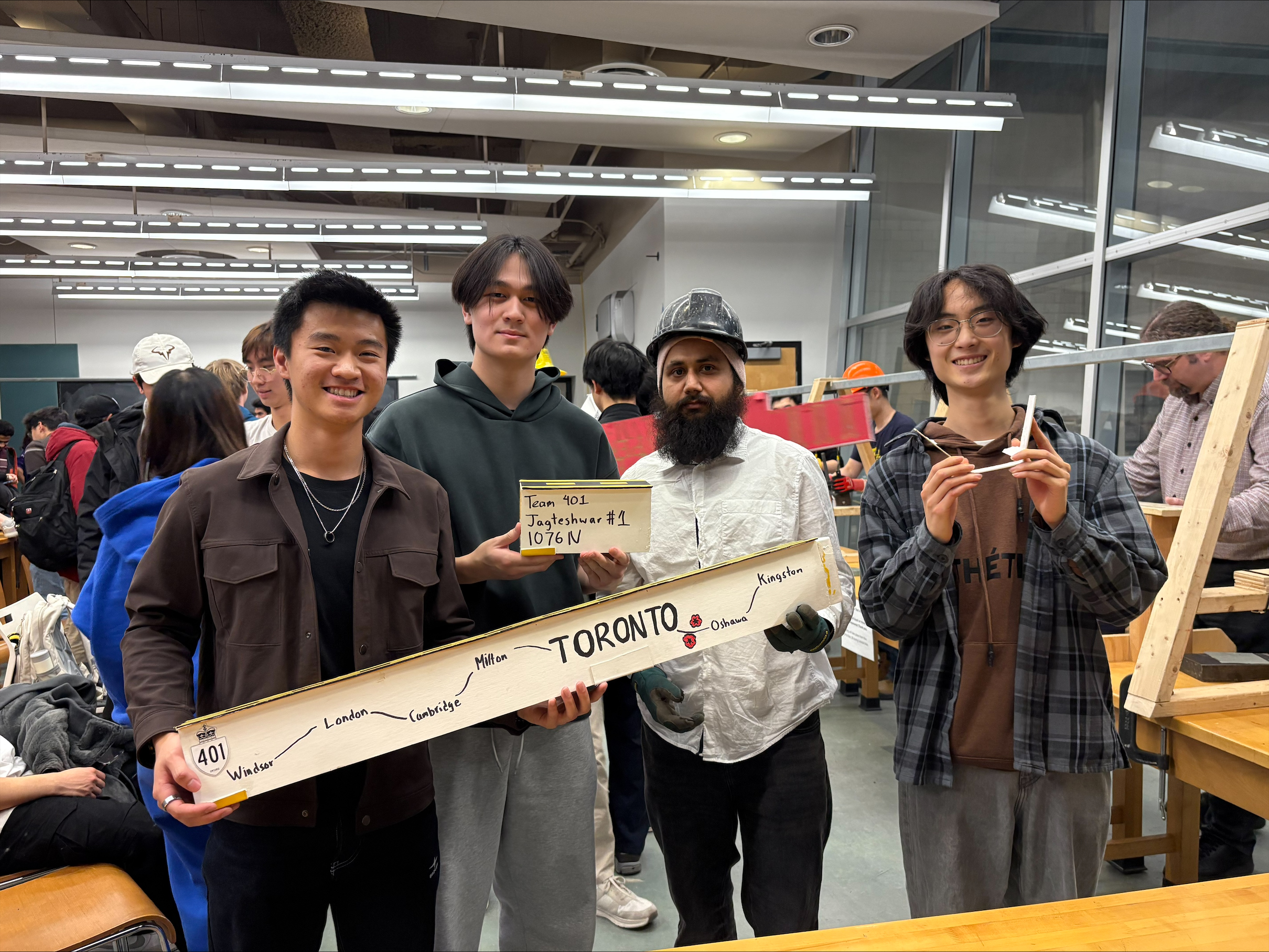
Figure 8. Group photo after bridge test. Bridge failed at 810 N.1 / 2
CTMFs from CIV102
4
Reference DesignsCTMF 4
What: The Observation
Analyzing a Reference Design ("Design Zero" in CIV102) is a framing and divergence strategy that involves breaking down an existing, baseline artifact to understand foundational structural load paths before attempting to create a novel solution. My evidence of use for this tool is a screenshot from our initial CIV102 engineering report detailing our analysis of "Design 0," which was a basic, unmodified pi-beam cross-section. The visual explicitly notes our mathematical discovery that this reference design catastrophically failed from Case 1 buckling in the top middle flange at a mere 257 N of force.Evidence of Use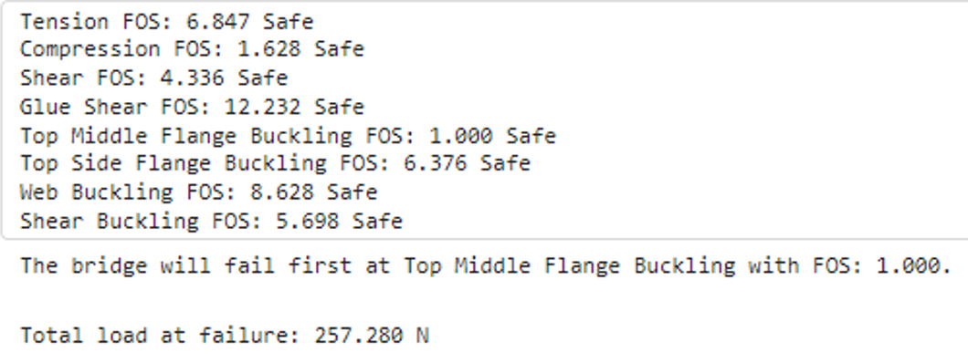 Figure 10. CIV102 report — Design 0 analysis. The baseline pi-beam fails at 257 N under Case 1 buckling, immediately identifying the top flange as the primary bottleneck.
So What: Analysis
For the "Optimizer" side of my engineering identity, starting with a Reference Design is an incredibly attractive tool. It bypasses the messy, abstract "guessing" phase of divergence and immediately provides a quantifiable baseline to improve upon. However, looking back, I realize this tool was a double-edged sword that severely restricted my team's creativity. Because we started our divergence phase by staring at "Design 0" (a pi-beam), my brain immediately locked into pi-beam optimization. All eight of our subsequent design iterations were fundamentally just mathematical tweaks to flange thickness, diaphragm spacing, and web height. We completely failed to diverge into radically different geometric shapes (like a box-girder or an I-beam) because the reference design acted as a psychological anchor. It optimized our process but killed our creative empathy.To prevent this premature convergence in my future career, I am instituting a strict personal constraint: I must independently sketch at least three completely divergent, radical concepts on paper before I am allowed to open historical reference design files.Relation to Position
This CTMF highlights the tension between the two halves of my "Empathetic Optimizer" identity. While optimizing a baseline is highly efficient, it actively suffocates the artistic, open-minded exploration I value. This tool affected my position by proving that premature mathematical framing kills creative divergence.At a Glance
Strength
Immediately quantifies where structural failure occurs, giving the team a precise, mathematically grounded starting point for improvement.Weakness
Acts as a powerful psychological anchor that locks the team into the reference geometry, suffocating genuinely divergent exploration of alternative forms.Takeaway
Use reference designs to understand failure modes only — never open them until you have already sketched at least three radically different concepts from scratch.5
Big A Authority / Perry's ModelCTMF 5
What: The Observation
In the context of Perry's Model of Intellectual Development, relying on "Big A Authority" involves recognizing the limits of one's own theoretical derivations and actively seeking out the lived, practical experiences of credible experts. My evidence of use for this is a side-by-side image in my engineering notebook: on the left, a screenshot of a past student's bridge catastrophically failing at the mid-span splice joint; on the right, a CAD sketch of our resulting "unique wrap-around splice," heavily reinforced with extra matboard. We arrived at this design only after intentionally consulting upper-year students.Evidence of Use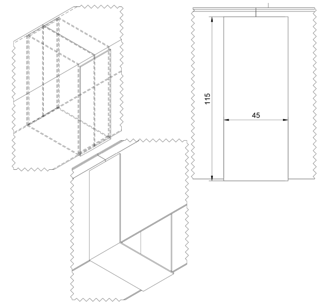 Figure 11. Reinforced wrap-around splice design, a solution invisible to pure mathematical modeling revealed by speaking to upper years.
So What: Analysis
My MATLAB script insisted that making the bridge incredibly tall would yield the highest Factor of Safety. However, when we consulted a second-year (a Big A Authority), he warned us that his incredibly tall bridge failed due to torsion — a twisting failure mode completely absent from our CIV102 curriculum, and therefore entirely invisible to my code. Furthermore, the upper-year students stressed that the glue splice is the ultimate point of failure, heavily dependent on human execution.Trusting their lived experience over my theoretical math saved our project; it led us to intentionally cap our bridge height to prevent twisting and to design a massive wrap-around splice to combat human error. In the end, our bridge performed third best in the class, with most other teams failing at the splice. Before I finalize the framing of any major structural project, I will mandate a consultation with a "Big A Authority" explicitly to ask: "What are the invisible, real-world failure modes that my math is blind to?"Relation to Position
This tool directly confronted my ingrained belief that "my knowledge and skills" were sufficient to solve any problem in isolation. It shifted my position by proving that inherited wisdom is just as vital as calculus. It keeps my Optimizer ego in check and grounds my designs in empathetic, lived reality.At a Glance
Strength
Some failure modes cannot be predicted mathematically or through simulation but require real world experience, so Big A Authority allows that information to be passed down.Weakness
The quality of the insight is entirely dependent on finding the right expert, it is easy to trust anyone that has more experience than me, but that can lead to blind trust that is not backed by disciplinary reasoning.Takeaway
Before finalizing any structural frame, it can be helpful to consult someone who has physically built and failed a similar system and ask specifically what the math cannot see, but also validate their information through research.6
Mathematical Modeling / SimulationCTMF 6
What: The Observation
Mathematical Modeling is a convergence and representation tool that involves creating a digital, equation-based abstraction of a design to rapidly simulate environmental loads and predict failure without the need to construct physical prototypes. My evidence of use is a screenshot of the custom MATLAB coding environment we built from scratch, showing calculated Factors of Safety (FOS) across all eight failure modes plotted directly alongside our generated Bending Moment Envelope. This tool allowed us to execute eight complete design iterations in the time it would have taken to manually cut and glue a single physical prototype.Evidence of Use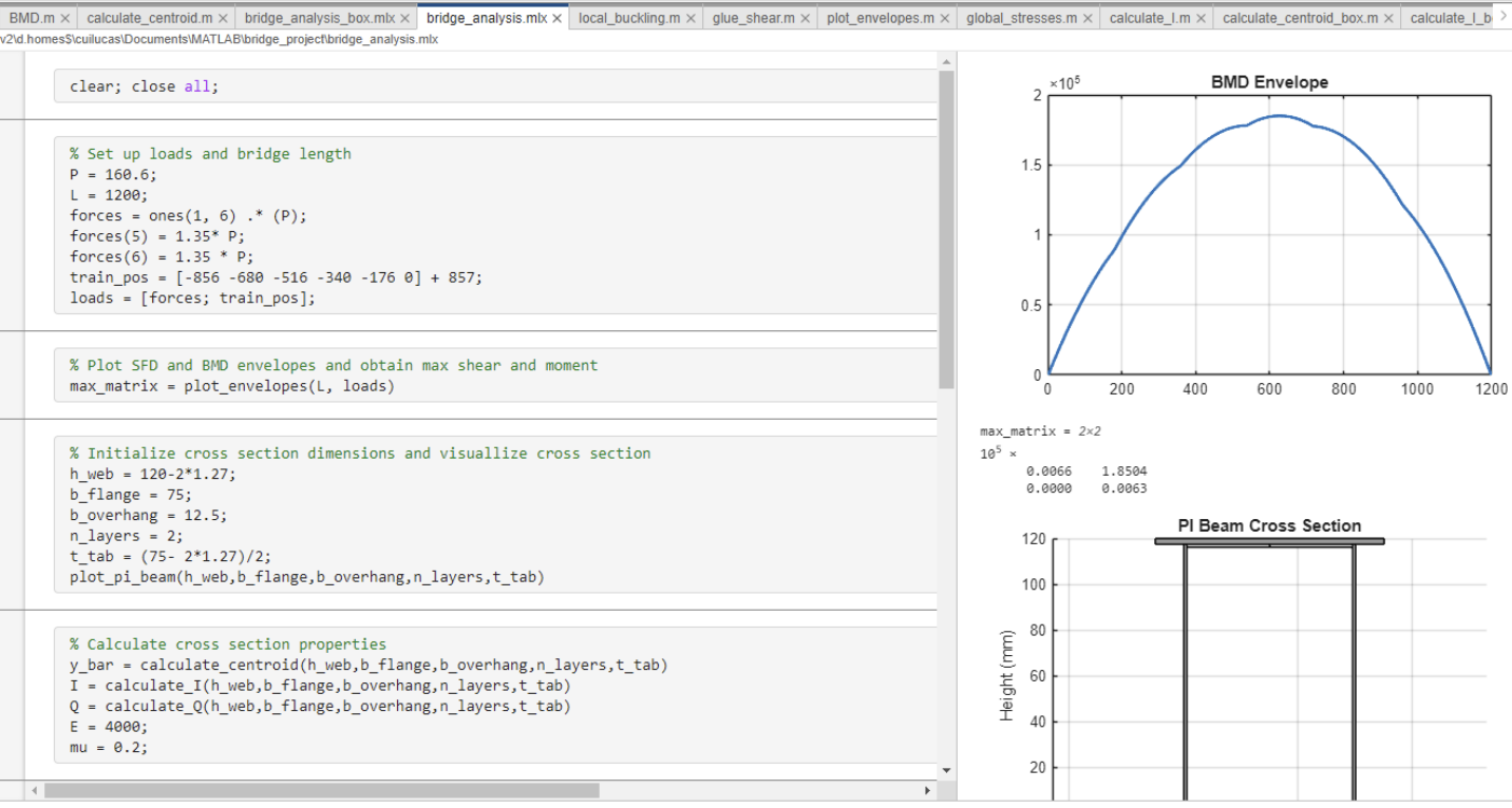 Figure 12. MATLAB simulation output — FOS values across all 8 failure modes alongside the Bending Moment Envelope. Eight full design iterations executed in the time one physical prototype would take.
So What: Analysis
Mathematical Modeling felt like the ultimate playground for my "Optimizer" identity. However, this project delivered a profound lesson on my human-centric blind spot: the builder is a user too. By Iteration 6, my MATLAB code had generated a mathematically brilliant bridge that could theoretically hold 1138 N. But when we went to physically build it, we realized the required glue tabs were so small and awkwardly placed that they demanded inhuman precision to assemble. The code assumed perfect 90-degree angles, flawless cuts, and mechanically perfect glue distribution. It lacked entirely the "Empathy" required to accommodate a tired student with a shaky hand.We ended up intentionally sacrificing our theoretical maximum load in Iteration 8, flipping the core 'U' piece upside down to create a continuous, highly accessible glue tab. For all future structural projects, I will always inject a "human tolerance variable" into my code — intentionally degrading my mathematical limits by 10–15% to buffer against the inevitable physical imperfections of the real world.Relation to Position
Mathematical Modeling expanded my definition of "Empathy." Previously, I only thought of empathy in terms of the end-user. This tool taught me Empathy for the Builder. It reinforced my position that relentless optimization is actually a design failure if it ignores the physical toll on the person assembling it.At a Glance
Strength
Enables eight full design iterations at the speed of a single keypress, compressing weeks of physical trial-and-error into an afternoon of scripted simulation.Weakness
The model operates in a frictionless, perfect world — it cannot simulate human hand tremor, imprecise cuts, or inconsistent glue application.Takeaway
Always inject a 10–15% human tolerance buffer into mathematical limits to bridge the gap between theoretical perfection and physical assembly reality.§ 4 — Praxis II Design ExperienceRock climbers use chalk to increase friction, but chalk piles onto holds, reducing texture and creating airborne dust. The opportunity was to help climbers at Basecamp safely clean Moonboard handholds from the ground while minimizing physical strain and harmful airborne chalk plumes.The design needed to restore a coefficient of friction (CoF) to at least 0.6, keep airborne chalk concentration under 25 µg/m³, and ensure the user's shoulder does not rise more than 60 degrees from a resting position.We diverged using biomimicry to move past standard brushes, developing concepts like the 'Clawcatcher' and 'Frog'. We reframed our scope specifically to the standardized Moonboard. We verified designs using a custom CoF proxy test and an air quality monitor. We validated concepts through four in-person visits to Basecamp.The "Fluffy Box". A 3D-printed, 18x11cm trapezoidal enclosure mounted on a 1.5-meter telescoping stick via a fluid ball joint. Internally, a motorized microfiber disk and sliding bristles rapidly clean the hold while the box entirely traps the airborne chalk.The Fluffy Box successfully restored the CoF to 0.72 and completely eliminated airborne chalk (0 µg/m³ compared to the 46.3 µg/m³ produced by a standard brush), all while requiring minimal shoulder movement.
The Fluffy Box
One-Page Project Summary
Opportunity
Frame
Process
Product
Result
Product Images
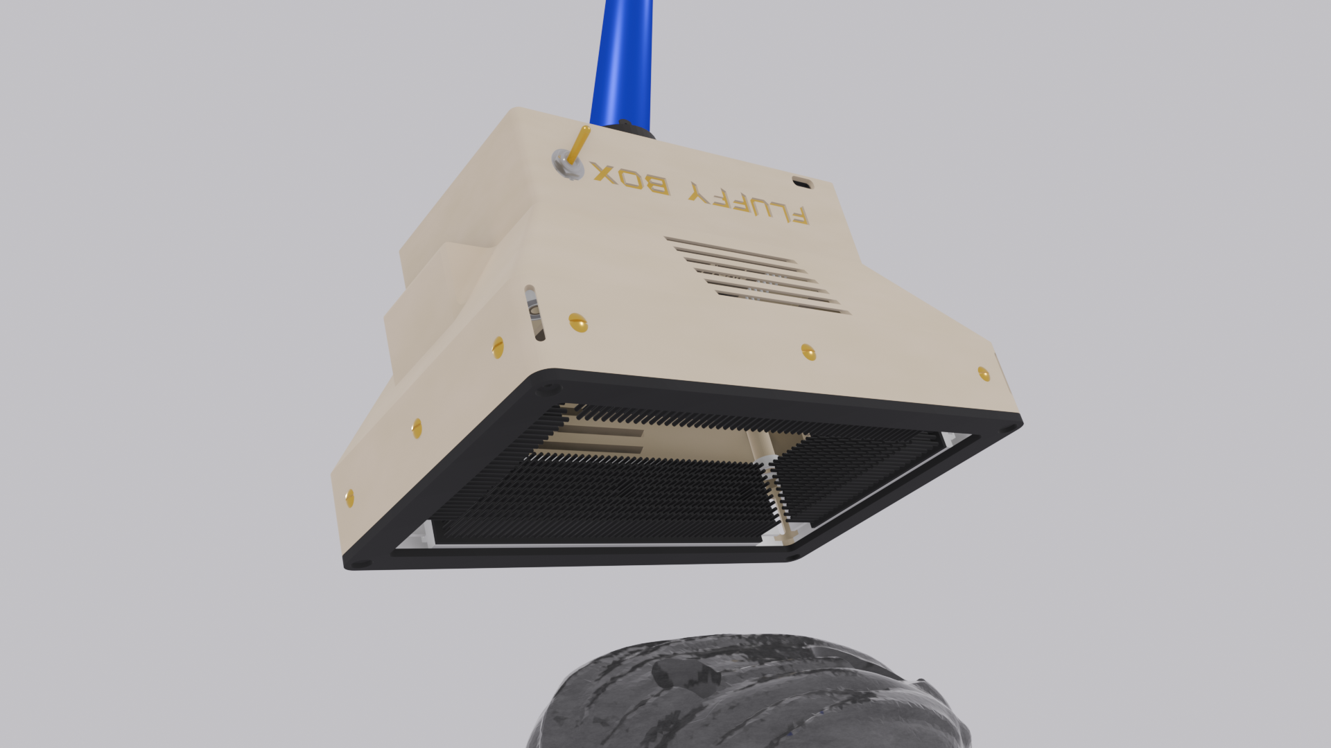
Figure 13. Side-view 3D render of final Fluffy Box prototype.1 / 3
CTMFs from Praxis II
7
Reframing Requirements & Evaluation CriteriaCTMF 7
What: The Observation
Reframing is the iterative process of critically analyzing and adjusting the project scope, problem definition, and metrics based on newly discovered constraints, stakeholder realities, and testability. It involves shifting from vague assumptions to actionable parameters. My evidence for this spans several key pivots: establishing a measurable proxy for "cleanliness" by restoring a coefficient of friction (CoF) to ≥0.6 on Moonboard holds; mathematically recalculating the target mass and height constraints to accurately reflect the physical realities of the climbing wall; and triangulating data sources for airborne chalk limits (the original RFP only provided one source, so we found multiple external studies that agreed to validate the metric). Finally, we reframed "neck movement" from a strict requirement into an evaluation criterion after stakeholder interviews revealed it was not a primary concern.Evidence of Use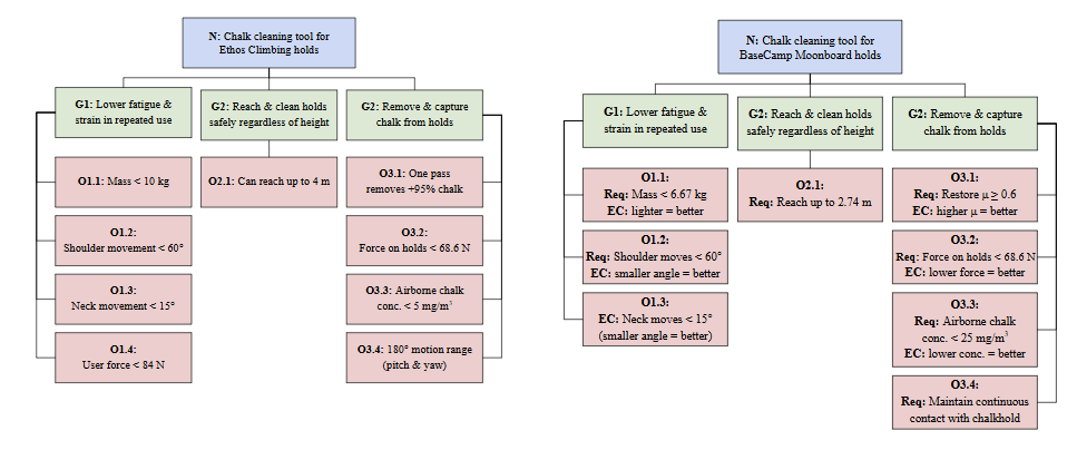 Figure 16. Reframing documentation — Left flowchart is NGOs from original RFP, right flowchart is our reframed Requirements and Evaluation Criteria.
So What: Analysis
This CTMF was vital for our project's survival and relevance. By mathematically reframing mass and height and triangulating airborne chalk sources, we created robust, defensible metrics rather than relying on the single point of failure in the original RFP. Moving "neck movement" to an evaluation criterion protected us from anchoring bias—preventing us from artificially restricting our solution space over a metric that climbers explicitly told us mattered far less than arm fatigue and chalk containment. I will use this CTMF in future projects whenever a design feels bottlenecked by the prompt; if I cannot physically test a requirement, or if stakeholders deem it secondary, I know I must proactively reframe the metrics to reflect reality.Relation to Position
Reframing ties directly to my core value of deeply understanding the right problem before attempting to solve it. It reflects my belief that good engineering is not stubborn compliance to a brief; it is adaptive and critical. Rather than forcing a solution to fit poorly defined or ranked constraints, I use reframing to ensure my efforts as an "Empathetic Optimizer" are directed precisely at the parameters that maximize real-world impact.At a Glance
Strength
Converts vague, untestable goals into precise, physically measurable metrics that unlock the design of effective verification protocols, while triangulating multiple sources makes those metrics far more defensible.Weakness
Reframing too narrowly can inadvertently exclude valid solutions — scoping exclusively to Moonboards risks missing a broader, more impactful design opportunity.Takeaway
If you cannot physically or mathematically test a requirement with the tools available, the requirement might not be specific enough. Reframe it until it is, and always validate new metrics against multiple sources rather than accepting the RFP's single reference at face value.8
BiomimicryCTMF 8
What: The Observation
Biomimicry is a divergence tool that involves looking to biological systems to inspire mechanical solutions in engineering design, leveraging nature's highly evolved adaptations to solve human challenges. My evidence is our team's ideation sketches: looking to nature led directly to the "Clawcatcher" concept (inspired by the grasping, encapsulating nature of human fingers) and "Frog" concepts (utilizing a sticky, ejecting mechanism similar to a frog's tongue).Evidence of Use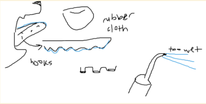 Figure 17. Biomimicry ideation sketches — Water-based solultions were ultimately eliminated.
So What: Analysis
During our early cycles of divergence, our team was suffering from design fixation—we were heavily biased toward the standard paradigm of "a brush on a stick that traps chalk," yielding only slight, uninspired variations. Biomimicry acted as a circuit breaker for this creative block, forcing lateral thinking. While the Frog concept was too mechanically complex, and we ultimately did converge back onto a stick-based handling mechanism (our "Fluffy Box" design), this exercise was incredibly valuable. Exploring radically different biological mechanisms gave us the comparative evidence needed to confidently justify why the stick approach was practically superior for user ergonomics. I will use biomimicry in future ideation sessions not just to generate novel ideas, but to pressure-test my default assumptions and build confidence in my final convergent choices.Relation to Position
This CTMF aligns perfectly with my commitment to an open-minded exploration of the solution space. As an engineer, my own imagination can easily be limited by the familiar machines and tools I interact with daily. By leveraging biomimicry, I expand my toolkit to include millions of years of natural R&D. It proves my willingness to look outside traditional silos to rigorously explore the design space, ensuring that when I do optimize a final design, it is chosen because it is truly the best option, not just the most obvious one.At a Glance
Strength
Breaks incremental, reference-anchored thinking by forcing the team to draw inspiration from biological systems that have no existing engineering equivalent, and the comparative exploration builds genuine confidence in the final convergent choice.Weakness
Biological analogies can lead to concepts that are too mechanically complex or biologically fragile to translate into manufacturable, durable engineering solutions.Takeaway
Use biomimicry as a circuit-breaker when brainstorming stalls — the goal is not to copy nature, but to extract the underlying principle and re-engineer it, and even concepts that are too complex to build can still validate why a simpler approach is the right one.9
Validation through Stakeholder InterviewsCTMF 9
What: The Observation
Validation through stakeholder interviews involves taking concepts and low-fidelity prototypes out of the lab and directly to the user's environment to gather qualitative feedback and co-develop the design. It centers on directly engaging with end-users to gauge real-world usability. My evidence stems from our four hands-on visits to Basecamp Climbing. This wasn't just formal questioning; we actively climbed alongside the staff and gym members, having them interact with our physical prototypes on the wall.Evidence of Use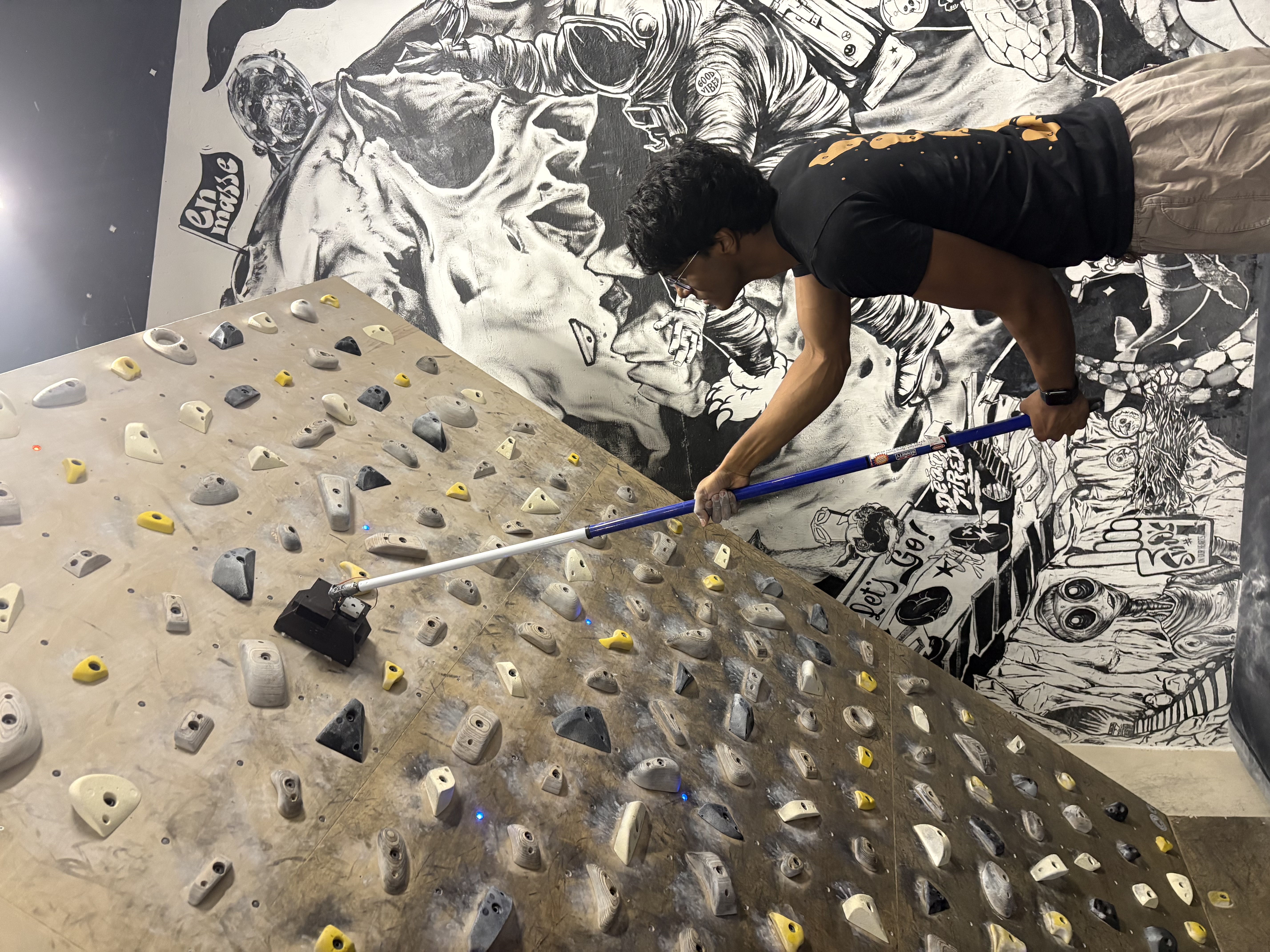 Figure 18. Photo of basecamp climber testing a fluffy box iteration.
So What: Analysis
This tool is the ultimate reality-check. While verification proves the device hits technical metrics, validation proves the device actually solves the users' pain points. Because I am a climber myself, our team had a massive potential blindspot: relying too heavily on my personal assumptions. Actively interviewing a diverse group of gym staff and climbers completely mitigated this bias. Furthermore, observing stakeholders' immediate, unfiltered reactions to the device actively drove our convergence. For example, their visceral reaction to the noise of our initial prototype motor led us to immediately swap it out, and their frustration with our rigid camera-mount inspired the flexible ball-joint adaptation. I will never design a user-facing product without early, tangible prototype testing with actual stakeholders.Relation to Position
This CTMF is the absolute cornerstone of my human-centered engineering identity. It proves that I do not design in a vacuum. By prioritizing empathy and embedding myself in the stakeholders' environment, I ensure my engineering decisions are driven by actual lived experiences rather than isolated technical assumptions. It reinforces my core belief as an Empathetic Optimizer: the best, most elegant designs are co-created with the community as active partners, not just built for them from afar.At a Glance
Strength
Surfaces qualitative failure modes — noise, rigidity, intimidation — that no quantitative metric or lab test would ever detect, and in-situ testing with rough prototypes yields far more honest, constructive feedback than polished demos ever could.Weakness
Small, self-selected sample groups at a single gym risk producing feedback that reflects that community's specific preferences rather than the broader climbing population.Takeaway
Validation and verification are not interchangeable — always run both, because a device that works in the lab can still be completely unwanted in the field, and the earlier you bring a rough prototype to real users, the cheaper and faster the resulting design pivots will be.References
[1] E. Bentz, “Course Project,” assignment document, CIV102: Structures and Materials - An Introduction to Engineering Design, University of Toronto, Toronto, ON, Canada, Nov. 2025. [Online]. Available: University of Toronto Quercus platform (restricted access).
[2] R. Carrick, J. Lofgreen, and A. Aubeeluck, “Requirements and Research - Lecture 6,” ESC101, University of Toronto, Toronto, ON, Canada, 2025. [Online lecture slides]. Available: University of Toronto Quercus platform (restricted access).
[3] R. Carrick, J. Lofgreen, and A. Aubeeluck, “Converging Strand - Lecture 27,” ESC101, University of Toronto, Toronto, ON, Canada, 2025. [Online lecture slides]. Available: University of Toronto Quercus platform (restricted access).
[4] R. Carrick, J. Lofgreen, and A. Aubeeluck, “Multi-Criteria Decision Making - Lecture 28,” ESC101, University of Toronto, Toronto, ON, Canada, 2025. [Online lecture slides]. Available: University of Toronto Quercus platform (restricted access).
[5] A. Zhang, “Position Statement,” University of Toronto, Toronto, ON, Canada, 2025. [Unpublished].
[6] A. Zhang, M. Ranaa, S. Zhang, and A. Bulatovic, “Design Report – Proposing a 2-in-1 Rotating Cylinder Design to Solve the Hassle of Preparing and Sorting Pills and Powders in the Morning,” University of Toronto, Toronto, ON, Canada, 2025. [Unpublished].
[7] “16 Diverging Tools,” ESC101, University of Toronto, Toronto, ON, Canada, 2025. [Unpublished].